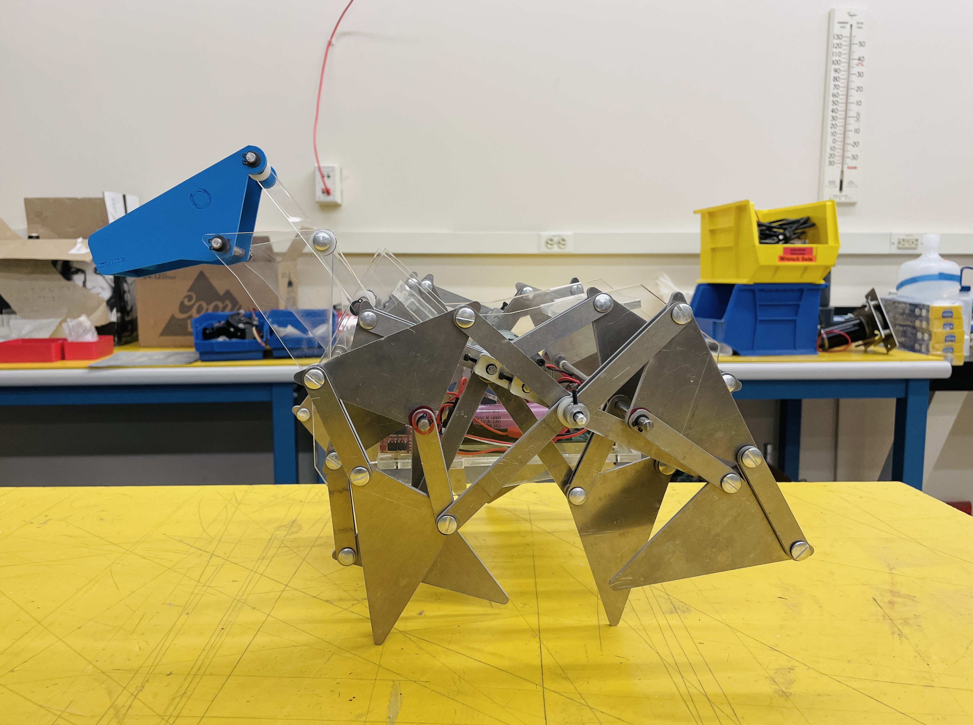
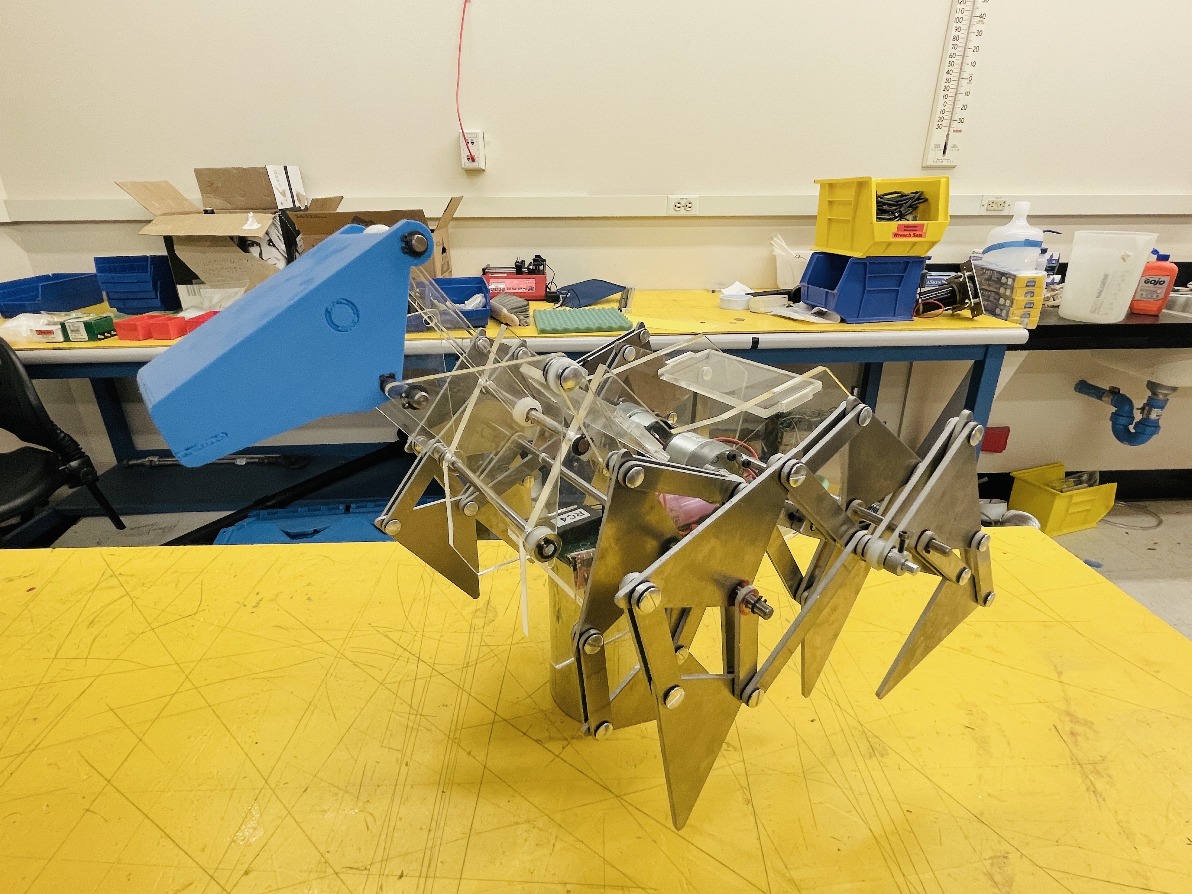
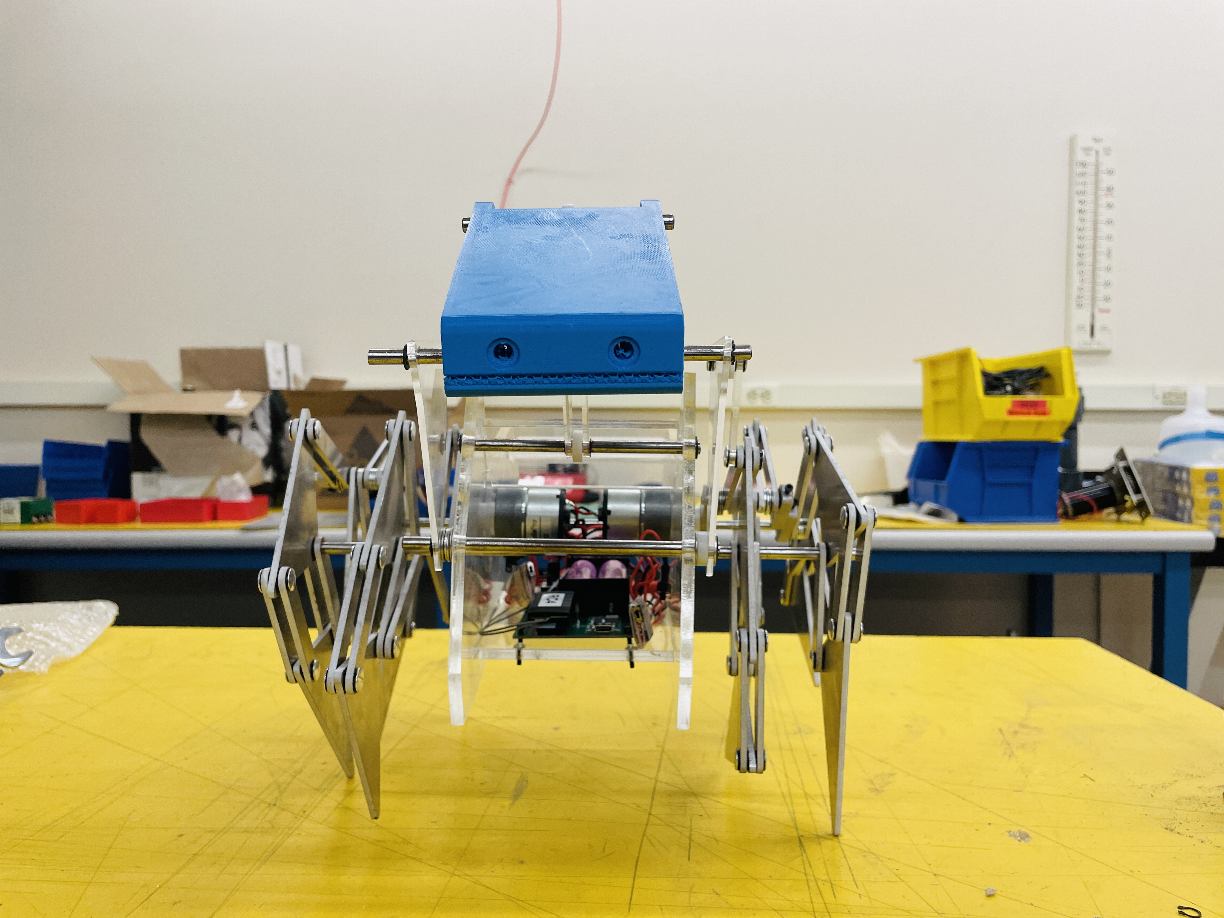
Mechanical Monster Horse

By Gigi Yeung and Asavari Saigal | Sunday, April 28, 2024

Have you ever wondered what a mechanical monster might look like? For this project, we were given the task of creating a walking “mechanical monster”, integrating 8-bar Theo Jansen linkages for the legs. These linkages were originally developed by Theo Jansen for the legs of his wind-powered mobiles. We were provided with a circuit board, two brushless DC motors, and a remote control for motor operation.
 

The Design

During the brainstorming phase, inspired by the motion of a horse, we decided to construct a horse shaped robot with four Theo Jansen linkage legs. We also explored the possibility of adding additional linkages to facilitate movement in the head.

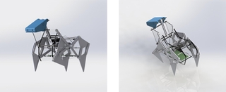
The initial design was made on SolidWorks using the leg dimensions provided by our instructor, Will Johnson. Following the design of the chassis, head, and neck linkages, we conducted a motion study in SolidWorks (as shown in the video below) to ensure that the neck linkages functioned effectively, enabling head motion. 

Animation of the motion in the head and neck linkages of the horse.

head

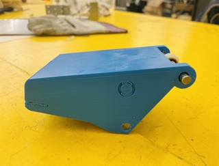
The 3D printed head. 

Upon checking the motion of the head and neck linkages, we proceeded to manufacture the components. The head was made using 3D printing, while the chassis and neck linkages were made through laser cutting. Thinking that it will be cool to have a transparent chassis, we opted to use  ¼” clear acrylic for the chassis. Originally, we planned to manufacture aluminum parts to join the two sides of the chassis. However, due to time constraints, we had to use laser-cut pieces for the connection. Each motor was mounted on a side of the chassis with M3 screws and connected to a pair of legs.

horse

The SolidWorks renderings of the design. 

Waterjet Cutting

After completing basic training on the waterjet, we began using it to make the leg linkages with 1/8” aluminum. The CAD drawing files were first uploaded into the Intell-MAX LAYOUT software to generate a machine tool path file, which was then opened in the MAKE software to direct the machine in cutting the material based on the X and Y coordinates. To minimize the risk of losing parts during the cutting process, tabs were integrated into the layout, thereby securing the parts to the aluminum sheet and preventing them from becoming loose. The waterjet cutting process is shown in the video below.

The process of using the waterjet to cut the aluminum parts.

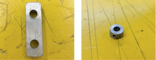
Additionally, we designed our own set screw collar and Part M of the linkage—a component securing the hex shaft to the motor axle. These parts were initially cut with the waterjet from 1/4” aluminum, and were subsequently drilled and tapped to accommodate 4-40 screws.

machine

Part M and the set screw collar.

assembly

Assembling the legs. 

Assembly

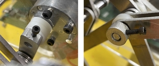
Following the cutting process, we assembled the leg linkages using Chicago bolts, spacers, and nylon washers. The legs were then connected to the hex shaft, which links to the motor, and a 0.25” rotary shaft that extends across the chassis to the other legs. Part M and the set screw collars were assembled at the ends of the hex shaft to maintain the position of the legs.

set scre

The assembled Part M and set screw collar. 

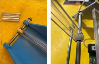
To secure the neck and head linkages, we cut small sections of the rotary shaft and fastened retaining rings onto the lines that had been slightly cut into each section to prevent horizontal shifting.

links

The linkages in the head and neck secured by retaining rings on a 1/4” shaft.

Testing

Upon completing the assembly, we tested the horse using the remote controller connected to the motors via bluetooth. By placing the horse on a stand, the leg motions and head linkages functioned as intended (shown in the video below). Unfortunately, the horse was unstable and unable to balance on its four legs on the ground when the motors were activated.  We then decided to add four additional legs to enhance stability and facilitate walking.

The motion of the horse with 4 legs.

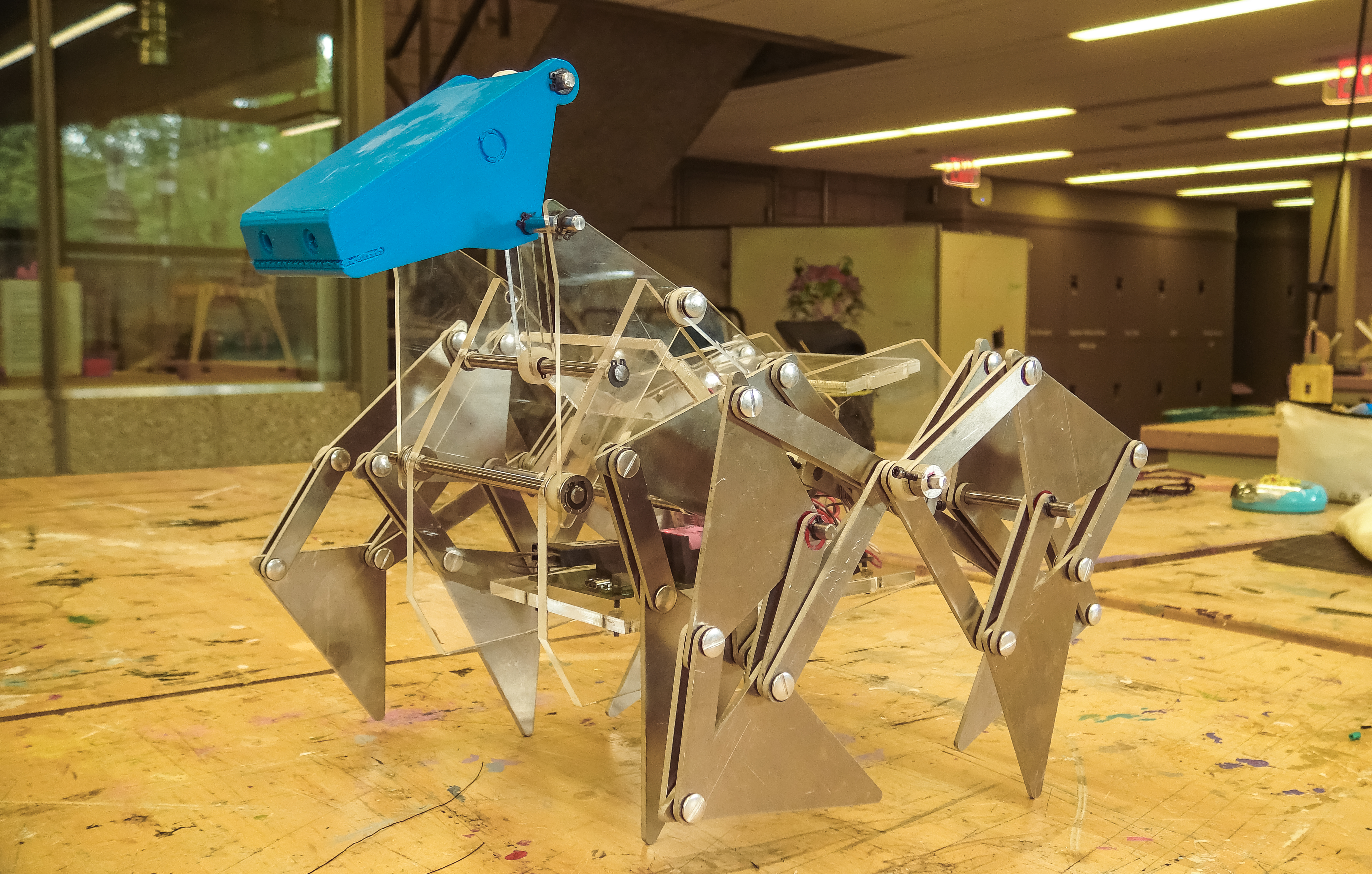
After manufacturing and assembling the additional legs, the mechanical horse not only achieved stability but also resembled a walking mechanical monster. The head movements were also successfully synchronized with the walking motion!

The Mechanical Monster

The finished Mechanical Monster in action.

The mechanical monster was a success, and we were extremely satisfied with the outcomes. Although we were unable to demonstrate the mechanical monster walking at Yale’s Undergraduate Senior Design Symposium, we still showcased our four-legged mechanical horse to peers and faculty members in the engineering department.

This project offered numerous valuable insights and learning opportunities. We not only mastered the use of the waterjet but also honed our skills in CAD, machining, and laser cutting. Despite the mechanical monster’s tendency to tip forward sometimes due to the heavier load at the front, we were still very pleased with the results and proud that we took extra steps to synchronize the head with the leg motion!