Crab Mechanical Monster!
Theo Janson Linkage

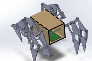
The Idea
The entire idea revolved around what we were given. We were given approximately 2 and a half weeks to make a “mechanical monster,” so our group had to find something that already resembled the shape. The legs were inspired by Theo Jansen’s Strandbeest. The chassis and the legs were already designed for us by the instructors of the course. Why not make a crab! Inspired by the gif below, we set off with our red chassis box and our eye design.
The circuitry was all done for us by the instructors of this course, but essentially, 2 Rechargeable Lithium Ion batteries power 2 brushless DC motors that are held in place to the chassis by M3 screws. The motors are controlled via Bluetooth, by the FlySky control.
Sebastian!!
I saw this gif one day and I knew this was it.
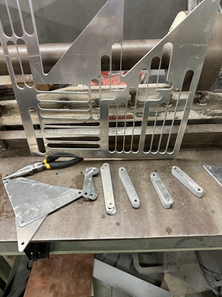
Water Jet Cutting
Our first order of business was creating the pieces for the crab’s legs. In order to do this, we utilized the water jet to cut our pieces out of aluminum. First, we were trained on the machine. Then, we put the water jet to use ourselves. We exported the CAD designed pieces that made up the legs to the water jet’s accompanying layout program. Here, we set the design up, as well as indicated the path the nozzle would cut. We then exported this file to the cutting computer program. Once our aluminum sheet was properly placed and secured in the machine, and the water level and nozzle were at the proper height, we began to cut, as seen in the video above.
Laser Cutting the Chassis
For the chassis of our mechanical crab, we used .125 inch red acrylic. Using the design created in CAD, we laser cut the acrylic, accounting for kerfs and overlaps in order for the pieces to properly press fit together, without the use of any fasteners whatsoever. In addition, we created two rectangles that stick out of the top of the chassis, giving us a place to put the eyes and sell the crab theme. The chassis houses the two motors, wires, and the circuit board. It also has holes in its sides specifically cut for the shafts and motors to properly and securely stick out of.
Assembly
Assembly of the crab, specifically the legs, was maybe the most time consuming part of the build. Each leg had several components, each that needed to be assembled in the proper order, using spacers, washers, and Chicago bolts. In addition, we had to use the drill and arbor press to fit our bushings into their proper location. Eventually, we got our legs assembled, and were able to see them move properly as seen in the first video below.
Next, we began attaching the legs onto the chassis. To do this, we had to tap the shafts through bushings, as well as attach and secure all the proper pieces where they belonged.
The Fails…
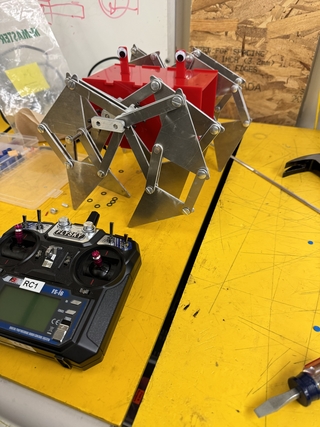
Diagnosing the Crab
Manufacturing took around 8 hours of our time. Assembly took that long, if not longer. The bushings wouldn’t fit on the shafts quite right, the legs would be assembled on backwards, the chassis kept breaking, etc. Below is us diagnosing the second pair of legs not moving. The way we got the crab to sit for us to do work was by placing the chassis on a stack of boxes that left the legs dangling.
The Legs Aren’t Moving Right…
The second pair wouldn’t move because we forgot the second crankshaft
And The Success!!
Look at HIM GO!!
It’s Walking!
The Takeaways
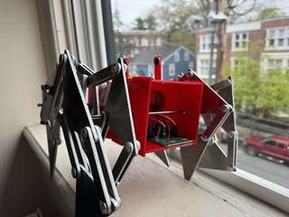
Photogenic Crab Shot
We were able to present the crab at Yale’s Undergraduate Senior Design Symposium! A waitress catering the event actually gave him the name Sebastian. We were able to show Sebastian, and other projects, off to friends and faculty in engineering! Very exciting to see a crab walking at an engineering symposium.
Obviously Sebastian isn’t perfect. The video reveals a bit of a lurch. He also simply collapsed at the end of his little walk because his legs weren’t synchronized well enough, causing him to tip forward. When he falls, the legs fold into themselves and he locks up. The solution to both of these issues is moving the crankshaft so their out-of-phase step causes his to maintain a stable walk. By far the largest thing we would do differently next time is redrilling out the holes cut by the waterjet cutter. They always ended up being a little too small. When we arbored press our bushings, the small holes caused the bushings to smush too much, causing them not fit on our 3/16 in shaft. Then, we had to hammer these tiny bushings in, and they would never be precisely where we wanted them on the shaft, and they couldn’t move, causing a lot of unwanted torque on the crab.
Other than that! This is was a great final project, and a great learning opportunity for us! A lot of effort was put into making sure it worked before our presentation at the Symposium, and we’re glad it paid off!