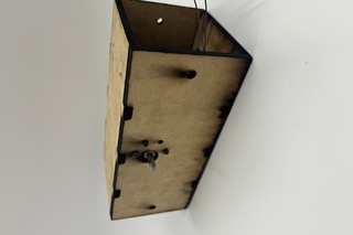
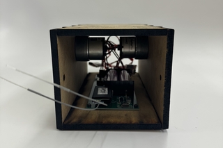
Once we had finished building all of our legs, we lasercut the chassis out of MDF, screwed in the motors and circuit board, and attached the legs to the motors. This was done using a series of small lengths of hex shaft, and the afformentiond crank legs with set screws. This was a rather delicate operation, as the crank shafts had to be at specific angles to ensure proper timing. We also encountered some brief issues where the legs were running into eachother, so we added spacers along the lengths of hex shaft to ensure that does not happen. Our biggest problem was adding the 2 axels that hold the legs apart. These go through the bearing in the leg, but when we used the arbor press to fit the bearings into the linkage, we must have smushed the top a little bit, shrinking the opening. As a result, the axels did not fit. So, we polished the axels down and drilled out the shafts, and with a little elbow grease (and real grease) we were able to get it to work!
Nayan Charlie Merrit Mechanical Monster
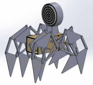
CAD and Basic Inspirations
The main part of the “strandbeest” is the Jansen linkage, an 8 bar linkage that contains a series of double rockers. The first step in our process was to CAD the linkage, run a motion study to make sure our link lengths worked, and then make an assembly of the full strandbeest (pictured). We also added a dartboard on top (didn’t quite make the final). As you can see, each side has 4 legs, 2 facing each way. We did this so that we would have 4 points of contact at all times to stay stable.
Base Linkage
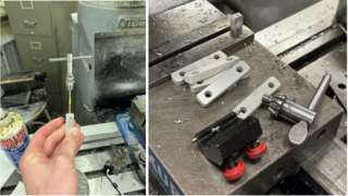
The next step was to build the jansen linkage. We used a waterjet and 1/8” pieces of aluminum. Pictured are the crank legs of the linkage. These were made of 1/4” aluminum. After waterjetting, we used a drill press and hand tap to create holes for set screws to secure onto the crank shaft. This piece ended up being a small pitfall, as our set screws would slowly grind away the shafts and as a result would start to slip.
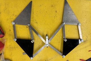
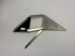
Completed linkage
Pictured is an example of the completed linkage. As you may notice, one of the pieces is not aluminum. It is lasercut 1/8” acrylic, because we did not have the metal or waterjet time to cut that piece. It is not loadbearing so acrylic in this case is completley fine, and preferable to mdf as it is slightly harder. The green “x” notes the location of a bearing. This is the only bearing in the linkage as the other joints are secured with chicago bolts. This bearing was the second pitfal.
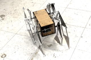
Final product
Crawling!
We got it to crawl! It has a few balance issues as it occasionally falls over, but for the most part, it works. In the future, we would double support each leg for stability and it would work great.