Charlie's Flash Drive
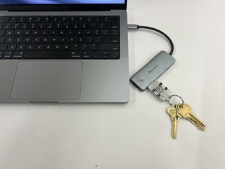
The Flash Drive In Use
Flash Drive Design & Manufacturing Process
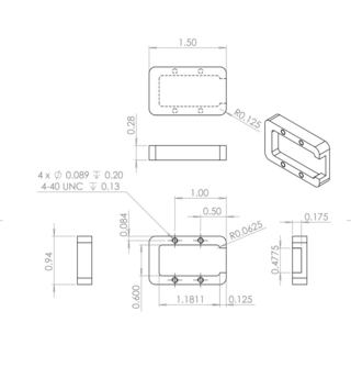
The Base
Using our instructor, Will Johnson’s, design and the help of Nick Bernardo in the Machine shop, I first machined the base for the flash drive using a CNC mill. The design includes four 4-40 threaded holes to accommodate four screws to secure a top to the base. The USB sits flush with the top of the base, allowing for the top to be a simple flat design. The corners are filletted for a more ergonomic design, but the top and bottom edges are right angles to keep manufacturing as simple as possible. The CNC milling process was straightforward, but still very involved. After squaring off the raw aluminum with a bandsaw, I placed the stock in the mill and zeroed the machine at its center. After uploading the tool paths to the CNC, I let the machine mill out the main pocket first. A tool change was required next to cut tighter radii into the inner pocket and drill out the four holes for the screws. Then, using a tap, I threaded the holes by hand and tested the threads with the proper screws. Finally, with a bandsaw, I removed the excess aluminum at the base of the part that had been used to hold it in place on the CNC mill.
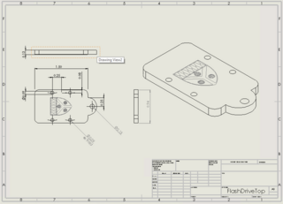
The Top
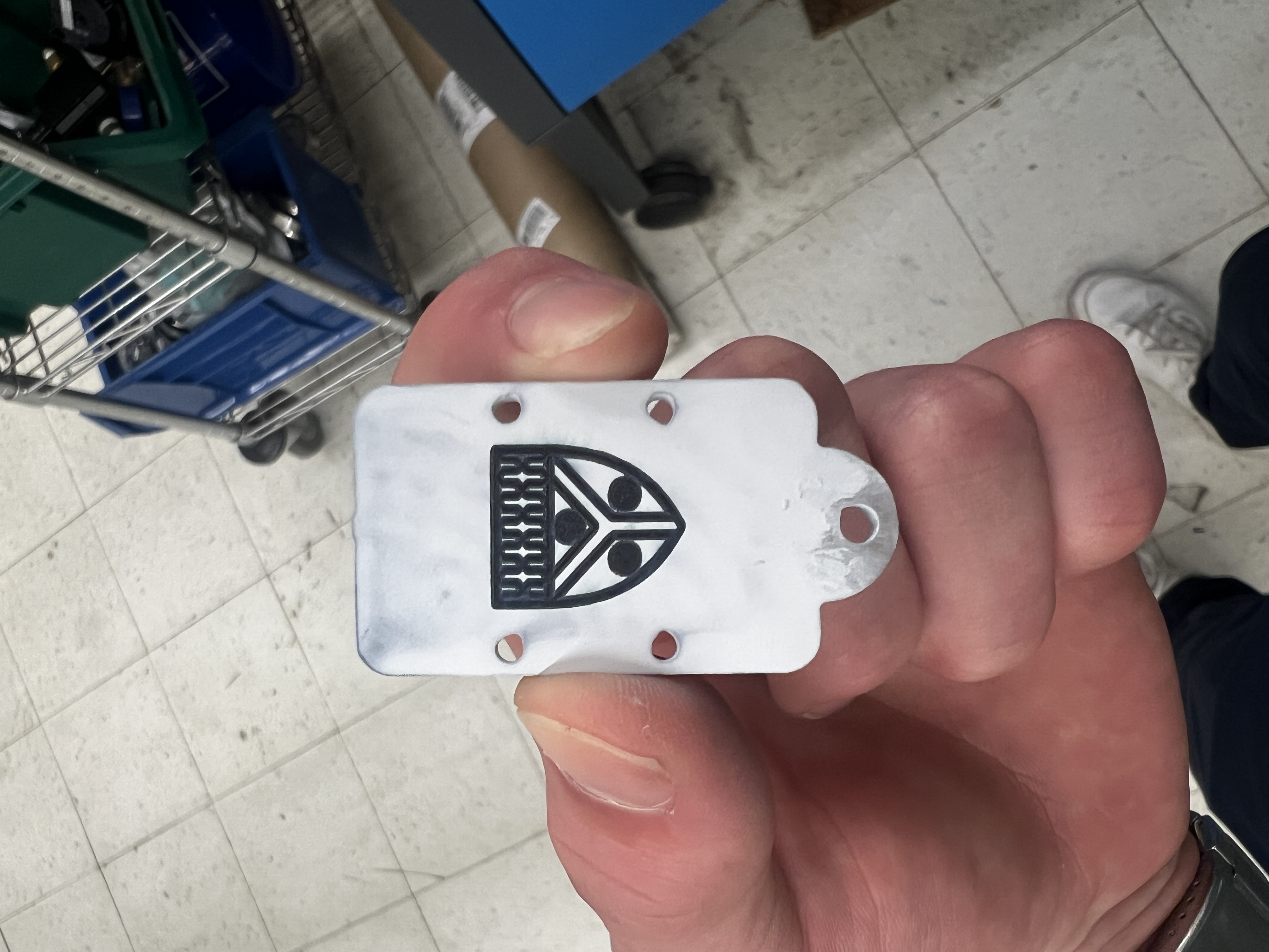
After considering numerous material options and manufacturing methods, I decided to water jet cut the top out of aluminum and then laser engrave the crest onto already cut piece using Omnitech laser engraving spray on the laser cutter. First, I designed the top on Solid Works matching the outer dimensions of the base and its four screw holes and adding a key ring loop to the back side. I decided to water jet cut out of 1/8” thick aluminum to keep the design sleek and be able to use the length of screw available. I uploaded a DXF file to the water jet cutter and added a tab to the front edge in order to not lose the small piece in the machine after the cut. After checking the tool path (screw holes cut first) and running through the machine’s start up check list, I successfully cut the flash drive top. After popping the part out of the sheet, I removed the tab using a belt sander. Next, I sanded the top with 600 grit sand paper smooth finish and prepped the surface with rubbing alcohol to ensure good adhesion with the Omnitech laser engraving spray. I uploaded a DXF file of the crest on the part that I had traced from an image in Solid Works to the laser cutter via Adobe Illustrator. After adjusting the laser cutter’s settings to engrave and meticulously zeroing the part on the laser cutter, the machine left a permanent black engraving of the SEAS crest. Assembly of the top and base was straightforward after further clearancing the top’s roughly water-jet-cut holes with a drill press.
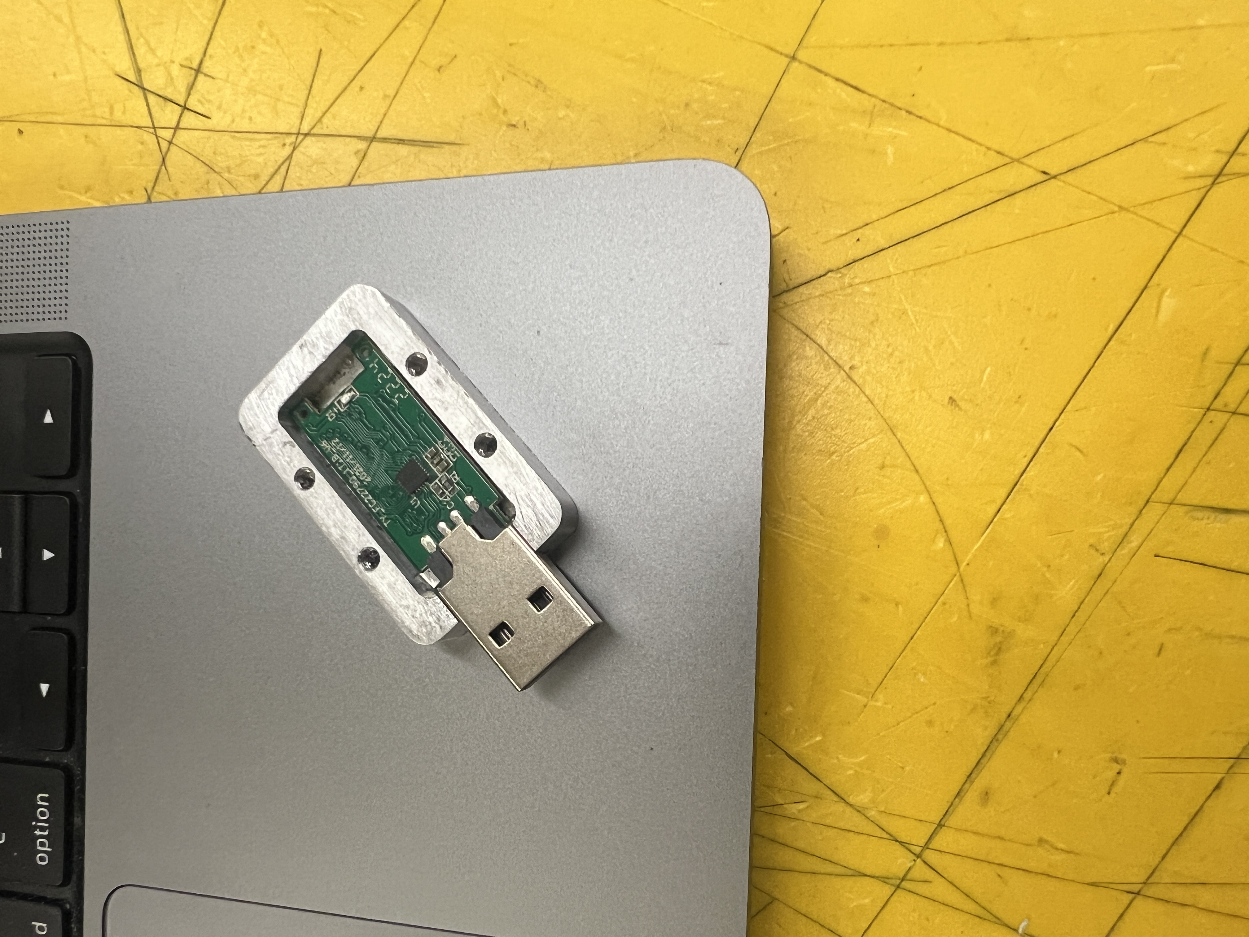
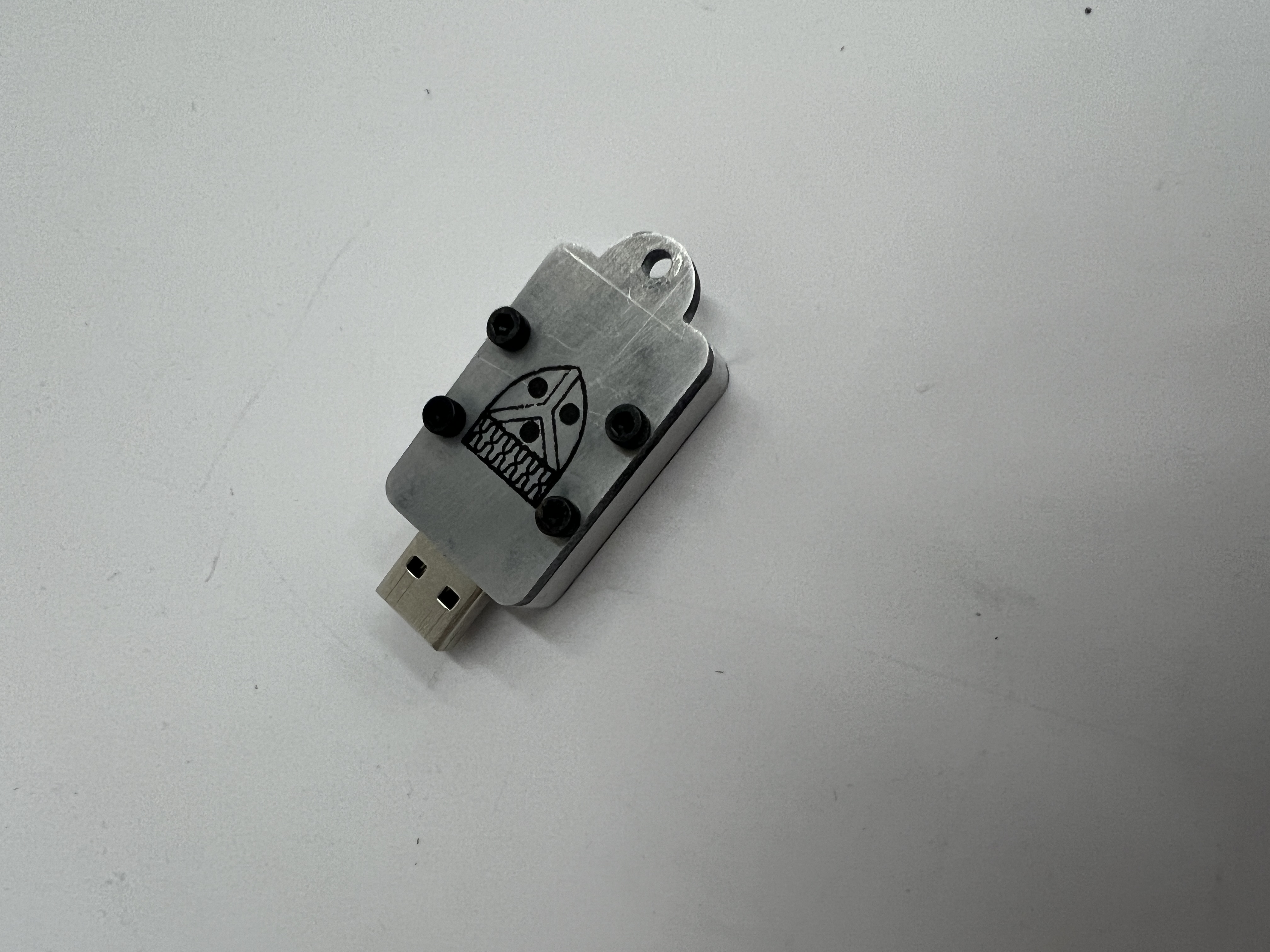
Flash Drive Parts & Assembly
3
Flash Drive Assembled
Takeaways
Compared to my other design projects, I am most proud of this final result. I was able to grow comfortable with Solid Works drawings, learn the fundamentals of operating a CNC mill and water jet, and use the laser cutter in a new way for laser marking engraving. Although my design is relatively oversized, it is still very durable and has a meaningful Yale memento engraved onto its top. The one feature I wish I could have incorporated had I had more time would be a clear acrylic window through the top (below the crest) in order to see the USB’s light flash to indicate proper ejection. One can still easily determine when it is safe to eject by looking at the computer screen, but this window would have added functionality. Furthermore, I would have liked to drill counterbores into the top in order to have the four screws sit flush. This, however, would have required thicker aluminum from which to water jet cut the top, which was unavailable at the time.