Most USB flash drives are just basic and ordinary, typically rectangular in shape. This inspired me to design and manufacture a custom and unique USB case. Starting with the standard rectangular design for the USB case, I explored ways to make it unique. Additionally, I wanted to incorporate an ergonomic touch to it, so I chose to shape the case like a flat oval.
Gigi's Flash Drive
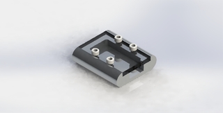
The photo-realistic rendering of the assembled USB case in SolidWorks.
The USB case was designed in SolidWorks and consists of two main parts: the bottom and the top.
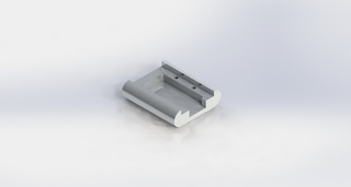
The design of the bottom part in SolidWorks.
The bottom part was machined from an aluminum block and features a filleted inside pocket where the USB would be placed. It also includes four 4-40 threaded holes that are used to connect both parts together with screws.

The design of the top part in SolidWorks.
I thought it would be interesting to be able to see the inside of the USB, so I decided to laser cut the top part using clear 1/8” acrylic. The holes in the top part are slightly larger than those in the bottom to ensure that the screws can fit through both parts. The dimensions of the holes were taken from the “Free Fit” section of the “Clearance Drill” category in the “Tap and Clearance Drill Size” chart.
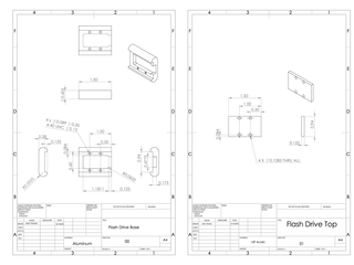
The engineering drawings of the two parts of my design: the bottom (left) and the top (right).
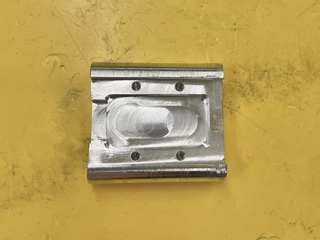
The finished bottom part.
After creating the drawings for both parts and receiving approval from our instructor, Will Johnson, I proceeded to the machine shop to cut the block of aluminum for the bottom part using CNC mills. The centre of the aluminum piece was set to (0,0) on the CNC mill to simplify the process of locating the edges and corners of the part; the desired dimensions and steps were then entered into the program. The initial step involved sculpting the aluminum into the part’s outer, round-shaped appearance by carving the corners and sides. Subsequently, the part was cut to the correct depth using the band saw, before the CNC mill was used to cut out the inner pockets of the part. After creating the inner pockets, four holes were drilled using the CNC mill. To complete the bottom part, the holes were then accurately tapped to the correct thread size using a drill tap.
The video shows the process of making the bottom part using the CNC mill.
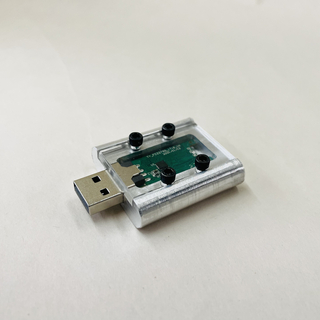
The finished and assembled case.
After the completion of the bottom part, the laser cutter was used to make the top part. The dimensions of this part had to be adjusted slightly to compensate for the kerf. However, due to inconsistencies encountered with the laser cutter, a single cut was insufficient and the program had to be executed twice. Additionally, the kerf appeared to be somewhat larger than anticipated, resulting in a slightly loose fit for the part. However, after assembling the part with the bottom and securing them with screws, the two parts managed to fit together, despite being slightly loose.
Designing and manufacturing this custom USB case offered an opportunity to acquire machining skills and become familiar with machining processes I previously had little experience with. It also enabled me to practice using CAD, creating engineering drawings, and operating the laser cutter. This project was rewarding, and now I have a unique USB flash drive for storing my future projects!