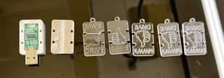
In order to accomplish my goal of uniqueness. I began my process of laser cutting my engraved cover. This task took me a good amount of tries as the laser kept cutting through the sides of the cover. I had to edit my CAD and reevaluate what the kerf of the laser was. I used the typical approach with engraving by changing the color in illustrator of my engraving.
MWW's thumb drive
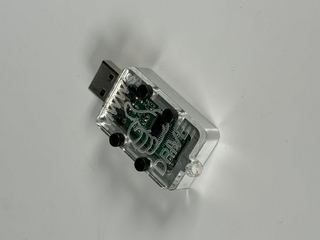
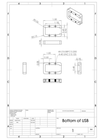
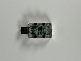
When initially being tasked to create a case for a usb, I started thinking about ways to make my project unique. I thought back to another way of describing a usb, a “thumbdrive.” I decided that I wanted to make a simple aluminum casing for the bottom and the top, but also create a laser cut acrylic top that had an engraved thumb on it. To start the assignment I began the CAD for my top and bottom of my case. Using the given dimensions of the bare usb, given by our teacher Will Johnson, I created the bottom with 4-40 threaded holes. It is a relatively simple design with the main pocket for the usb to sit in and then an opening for its end. I filletted the corners of the case to make it a more smooth object. The top used the same dimensions for the bottom, but was just an extruded sketch of the outline of the bottom. I used four holes for the screws to slide through to connect with the base.
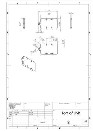
To find the dimension of these holes I used a tap chart and navigated to the 4-40 “free” section. Then I used my two CAD files to create drawings of my two parts. I included all of the appropriate dimensions and views in my drawings.
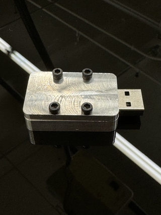
The next step was to use the CNC to cut both pieces. To start this process I had to input the steps the CNC would take to cut my parts. I set the (0,0) of the CNC to be the center of the piece of aluminum. This allowed the math for the locations of corners and holes to be significantly simpler. I was able to find one of the corners or locations of the holes and then change the sign of the x and y component of the location. I also learned how to make the machine notify the user to change the tool that the mill had attached. This is a crucial step because if the mill was using a drill bit that was not the correct one it would completely mess up the process. This experience with the CNC taught me a lot about its basic operations. I now understand that the CNC is very capable when cutting lines and arcs in the x and y direction, but arc in the z direction it cannot easily complete.
The next step for my thumb drive case was to tap the holes. I used a 4-40 tap for each of my four holes. I discovered that using the tap vice it was very easy to notice that the tap had reached the bottom of the hole. In order to avoid this, which could potentially break the tap, I started the process with the tap holster and then twisted it by hand until I felt the bottom of the hole.
The next step for my thumb drive case was to tap the holes. I used a 4-40 tap for each of my four holes. I discovered that using the tap vice it was very easy to notice that the tap had reached the bottom of the hole. In order to avoid this, which could potentially break the tap, I started the process with the tap holster and then twisted it by hand until I felt the bottom of the hole.
For the top of my case I used the CNC again to cut its shape and spot the holes. The first step was to make the part the correct thickness. I used the regular mill to “mow the grass” to achieve my desired thickness. To shorten the time with the CNC I kept my commands from the bottom but just deleted the pocketing functions. I then used one of the drill presses to make the holes themself. Lastly I used the chamfer drill to add chamfers to the top of my part.
