Custom Kerf Program
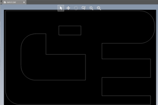
To deal with the kerf, I could have designed the tabs to all be adjusted in the CAD model but this would quickly become a nightmare in the assembly as parts would clearly not mesh correctly. So instead, I decided to try and write a program that would analyze the exported DXF file and output a properly adjusted DXF file so that the cut part would have the exact dimensions as the CAD model.
To do this, I first found a library that would allow me to interface python with the DXF file format. After some experimentation, I found that the library interprets the DXF as a series of lines and arcs, each with starting and stopping points (or angles.) To get the result I wanted I would need to 1) Find and separate the CLOSED shapes in the DXF file, 2) Analyze the shape to see which lines would need adjusting due to the kerf, 3) Combine all of these closed shapes onto a final DXF file.
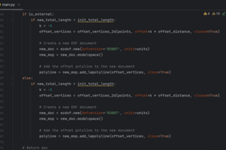
After a few days, I was able to write the script to accomplish this. The full script is 528 lines of code. Closed shapes were determined by iterating over each line or arc element, then all arcs were approximated with a large amount small line segments so I can fit a Polyline (a group of lines) over each closed shape, logic was used to determine which sides of each line were external or internal and this was used to determine how much the line should be adjusted. Finally, the adjusted polyline shapes were combined and returned as one DXF file.
